
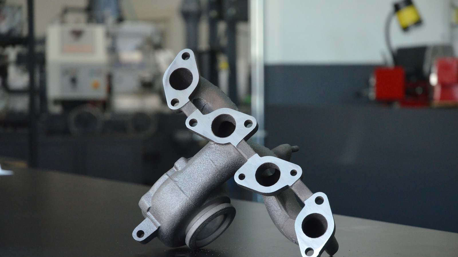
Oil leakage is one of the most frequently misinterpreted turbocharger symptoms. Oil at the compressor outlet or turbine side may originate from internal damage, but it can also result from an external pressure imbalance, restricted oil return, excessive crankcase pressure, intake restriction or an engine condition that changes gas flow around the sealing system.
A reliable investigation therefore treats the turbocharger as part of an integrated air, exhaust and lubrication system. This article outlines a failure-analysis method for workshops, distributors, product teams and quality engineers, from evidence collection to component validation.
Turbocharger sealing is a system function
Pressurised engine oil enters the centre housing to support and cool the bearing system. It then collects and returns to the sump by gravity. At the compressor and turbine ends, oil control is influenced by rotating oil-management features, close clearances and pressure relationships rather than a simple static lip seal.
This distinction is central to root-cause analysis. When drainage capacity falls or centre-housing pressure rises, oil may migrate toward either end even though the sealing components are not the primary defect. Garrett’s technical material describes oil leakage as frequently symptomatic of another vehicle problem, while BorgWarner identifies restricted drains and excessive crankcase pressure among the first checks.
Define the leakage location and operating state
External leakage
External wetness should be traced from a clean, dry assembly. Confirm whether the first wet point is the feed connection, drain flange, centre housing, nearby engine joint or a hose carrying oil mist. Gravity and airflow can move oil far from its origin.
Compressor-side contamination
Document the condition upstream and downstream of the compressor. Oil upstream may indicate crankcase-ventilation carryover. Oil downstream may come from the turbocharger, but its quantity and distribution must be compared with charge-air cooler condition, engine oil consumption and the history of earlier failures. Residual oil can remain after a previous repair.
Turbine-side contamination
Oil in the turbine housing or exhaust can be confused with oil entering the cylinders through valve guides, rings or liners. Record whether smoke occurs at start-up, idle, load or overrun. Soot, wet oil and carbon deposits represent different thermal histories and should not be grouped as one symptom.
A failure-analysis sequence
1. Freeze the evidence
Before cleaning or dismantling, photograph the installed orientation, pipes, clamps, actuator, nameplate and contaminated areas. Record oil level, mileage or hours, fault codes, boost data, oil consumption, recent engine work and the exact operating event. Retain relevant filters and oil samples when contamination is suspected.
2. Establish product identity
Capture the complete turbocharger manufacturer number, OE number, engine code and chassis/VIN. Record the actuator identifier and software or calibration references when applicable. Similar housings can contain different aerodynamic stages, bearing arrangements, actuators or connection geometry. A visual match is not a valid product identification method.
3. Evaluate lubrication supply
Inspect the feed line for restriction, contamination, internal delamination, incorrect fittings and excessive sealant. Measure pressure or flow only with the specified equipment and test point. Compare results with the engine and turbocharger application data, not with a generic value. A high reading can be as relevant as a low one because oil control depends on the approved system configuration.
4. Evaluate gravity drainage
Inspect the return line internally. Look for carbonisation, gasket overlap, bore reduction, sharp bends, distortion and incorrect housing orientation. Confirm that the route falls continuously and that the sump connection is not compromised by oil level or rotating oil inside the crankcase. Drain performance is a combined function of geometry, oil condition, temperature and crankcase pressure.
5. Quantify crankcase pressure
Check the breather, separator and associated hoses, then measure crankcase pressure at the specified speed, load and temperature. Distinguish a blocked ventilation system from genuine excessive blow-by. If ring, liner or cylinder condition is the root cause, fitting another turbocharger will not restore the intended pressure balance.
6. Assess intake and exhaust boundary conditions
Measure or inspect air-filter restriction, compressor-inlet deformation, charge-air leakage and exhaust restriction. Review aftertreatment condition and variable-geometry control where fitted. These systems influence mass flow and pressure at the turbocharger ends. A product returned for “oil seal failure” may therefore pass dimensional inspection if the vehicle boundary conditions are not reproduced.
7. Inspect the rotating assembly
Check wheels for foreign-object impact, erosion, rubbing, heat effects and deposits. Measure radial and axial movement using the manufacturer’s method and limits. Do not treat unpressurised movement in a floating-bearing design as failure without the correct specification. Preserve deposits and fracture surfaces if laboratory review may be required.
Failure modes that can produce similar symptoms
- Restricted oil return: oil accumulates in the centre housing and migrates toward compressor or turbine.
- High crankcase pressure: return flow is opposed by pressure in the sump or crankcase.
- Breather oil carryover: oil enters the compressor inlet and is misattributed to the turbocharger.
- Intake restriction: abnormal compressor-inlet pressure contributes to an unfavourable pressure balance.
- Engine wear: blow-by raises crankcase pressure and combustion oil consumption can imitate turbine-side leakage.
- Contaminated or degraded oil: bearing wear and carbon deposits can create both primary and secondary damage.
- Incorrect installation: housing angle, drain geometry, gasket position or line selection can impair return flow.
- Internal turbocharger damage: bearing-system wear, wheel contact or housing damage can be the primary cause once external systems are excluded.
From returned part to quality conclusion
Separate observation from cause
“Oil present at compressor end” is an observation. “Defective seal” is a proposed cause. A good report keeps these separate until evidence supports the relationship. This prevents a visible symptom from becoming an unsupported warranty conclusion.
Use a structured teardown
Record as-received condition, identification marks, actuator state, fastener evidence and deposits before cleaning. Measure critical features with calibrated equipment. Where appropriate, examine bearing surfaces, thrust components, wheel contact, oil passages and carbon distribution. Retain traceability to photographs and measurement records.
Compare with production and application data
Review dimensional results, balance records, material or process documentation and end-of-line test data when available. Confirm that the returned number belongs to the stated engine and vehicle application. A correct product can fail in the wrong application, and an incorrect product may create symptoms without an intrinsic manufacturing defect.
Validate corrective action
If the root cause is product-related, corrective action should address the controlling characteristic and include verification. If the cause is external, the report should state the required vehicle-system checks. In both cases, the result should be technically reproducible rather than based on substitution alone.
Design and validation considerations
Product-development and supplier-quality teams should consider oil-flow capability, drain orientation, crankcase-pressure envelope, hot shutdown, thermal cycling, oil contamination and the intended duty cycle. Validation must reflect application-specific boundary conditions. A bench test that confirms leakage control at nominal conditions may not reproduce a restricted drain or abnormal engine blow-by.
Traceability should connect product number, build lot, key process checks and test results. Packaging and handling also matter: damage to an actuator, open oil port or foreign material introduced before installation can invalidate otherwise sound manufacturing controls.
Information required for technical matching
A technical enquiry should include the full OE number, turbocharger manufacturer reference, engine code and chassis/VIN. Add the actuator number, vehicle model year, emission level and photographs of every nameplate. For an investigation, include operating hours, oil specification, maintenance history, pressure measurements and the installed drain orientation.
Compatibility must be confirmed for the exact engine and vehicle configuration. Housing resemblance, wheel size or a partial reference is insufficient.
Frequently asked questions
Is a turbocharger oil leak always caused by worn seals?
No. Restricted drainage, high crankcase pressure, breather faults, intake restriction and engine wear can create the same visible symptom.
Why can a new turbocharger leak immediately?
If the original root cause remains—such as a blocked return, contaminated feed or excessive blow-by—the replacement unit can show the same symptom. Installation and system checks are part of the repair.
Can shaft play be used as the only acceptance criterion?
No. Movement must be measured by the specified method and interpreted with wheel condition, bearing evidence and application limits.
What should a supplier receive with a returned unit?
Provide identification, chassis/VIN, engine code, installation photographs, operating data, service history and test results. A part without application evidence limits the quality conclusion.
Should oil lines be reused?
Follow the engine and turbocharger manufacturer’s instructions. A line that is contaminated, carbonised, damaged or internally restricted can compromise a replacement even if its exterior appears acceptable.
Technical component enquiries
For product-development, quality or technical matching discussions, review Astroline’s Products and Quality pages. Submit the complete OE number, engine code, chassis/VIN and manufacturer reference through Contact. Product suitability is reviewed against the supplied application data; no compatibility should be inferred from appearance alone.